This all started back in vocational school. The teacher asked us to program on some little project for a month and then show it in the class. So uhm… I thought: why not do a little bit more?
I was thinking a bit about what I could do and figured I haven’t done a hardware project in quite a while. So at some point I decided to get out KiCAD and start designing. As with most of my pcb projects, it has to have a ESP32! So I thought a bit and came to the decision that I do not have enough RGB in my life yet.

That is the basic schematic I came up with. Nothing too fancy. Just a ESP32 (WROOM-32E, to be exact), some components for flashing it and of course, lots of LEDs! It also has a buzzer and the ability to either use a SHT-30 or BME280 sensor for temperature / humidity.
The PCB also comes with a P-Channel MOSFET that is used as a reverse polarity protection.
Most features are optional, meaning they can be connected / disconnected via jumper pads. Those also are configurable in the config file of the software (built-time).
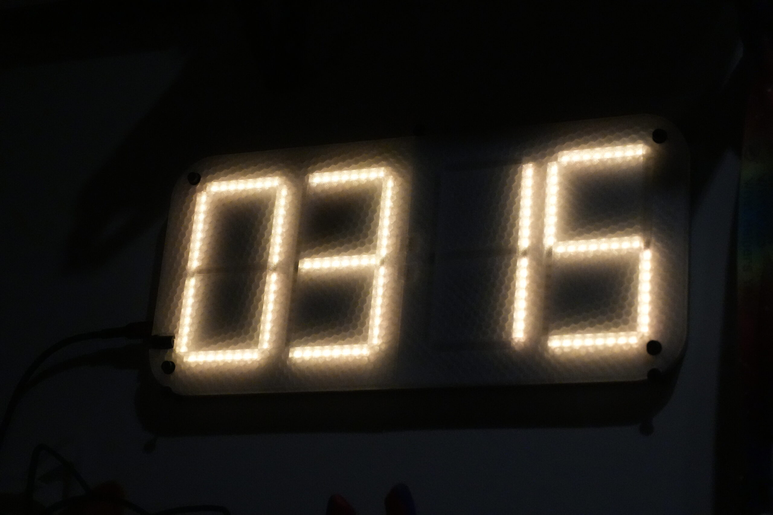
In total there are 232 LEDs (ws2812b) arranged as four 7-segment digits with two dots in the middle for blinking when a second passes.
The PCB design was done by hand because I did not know how to use the KiCAD features to help with arranging the LEDs. All positions are measured tho so it should be fine.
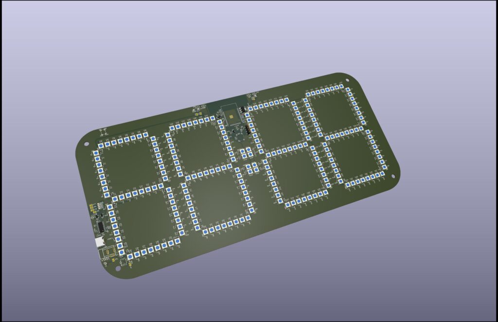
The picture above is actually the 2nd revision. In the first revision of the PCB layout, I unfortunately did not think about proper routing as much as I should have. The problem was that I had some traces going through one of the huge copper planes nearly the complete height of the pcb, which of course „bottlenecked“ the current flow. The 2nd revision fixes this by routing those traces at the edge of the pcb.
I am using both layers for powering the LEDs. One layer is +5V and the other GND. Both are connected to the USB port / barrel jack through the P-FET. Considering a single WS2812B draws around 60mA at max brightness, this pcb could theoretically draw 16A. Oops.
The only problem in the 2nd revision was a slight mistake which was easily fixable. It looked something like this (please excuse my drawing over it, I could not find a clean image):
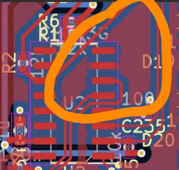
The problem essentially was just a unconnected copper area that for some reason did not throw a DRC error. But what would it be without a small bodge!
As for the software, it is completely custom made and based on the ESP-IDF. While in theory this project could also be done using ESPHome or WLED, using a completely custom firmware allows for better feature integration and less hacks.
The firmware also includes a webinterface, that is used for changing some settings or doing a OTA update.
Last but not least, there are some 3D-printable files. While the clock works without those, they make for a nice case that also diffuses the light in a cool way!
If you are interested, feel free to check the repo here:

A simple pcb clock using ws2812 in 7-segment form